Gerrit Niezen

electronics

Feature image

Yesterday we looked at how to connect to the USB host shield and read the register that contains the chip revision number. Today we'll look at how to initialise the USB connection with the device.

We already have a way to read registers on the USB host controller chip, but we also need a way to set registers:

setRegister(register, command) {
    SPI1.write([register | 0x02, command], D10);
}

It's similar to reading a register, except that we use the SPI1.write command since we're not expecting anything to be returned. We also send the SS pin D10 as a parameter. Now we can define some constants and set up full-duplex communication:

const REGISTERS = {
  RCVFIFO: 0x08,
  SUDFIFO: 0x20,
  RCVBC: 0x30,
  USB_CONTROL: 0x78,
  CPU_CONTROL: 0x80,
  PIN_CONTROL: 0x88,
  USB_IRQ: 0x68,
  IRQ: 0xc8,
  MODE: 0xd8,
  HIEN: 0xd0,
  PERADDR: 0xe0,
  HCTL: 0xe8,
  HXFR: 0xf0,
  HRSL: 0xf8,
};

const OPTIONS = {
  LEVEL_INTERRUPT: 0x08,
  FULL_DUPLEX: 0x10,
};

setRegister(REGISTERS.PIN_CONTROL, OPTIONS.FULL_DUPLEX | OPTIONS.LEVEL_INTERRUPT);

Those are not all the registers that are available. We'll add to the list as we go along. For the full list of registers see Table 2 in the MAX34321E datasheet. Now we need to reset the chip:

const COMMANDS = {
  CHIP_RESET: 0x20,
};
    
reset() {
  this.setRegister(REGISTERS.USB_CONTROL, COMMANDS.CHIP_RESET);
  this.setRegister(REGISTERS.USB_CONTROL, 0x00);
  let i = 0;
  while((this.readRegister(REGISTERS.USB_IRQ) & 0x01) === 0) {
    i++;
  }
  console.log(i, 'attempts to settle');
  return i;
}

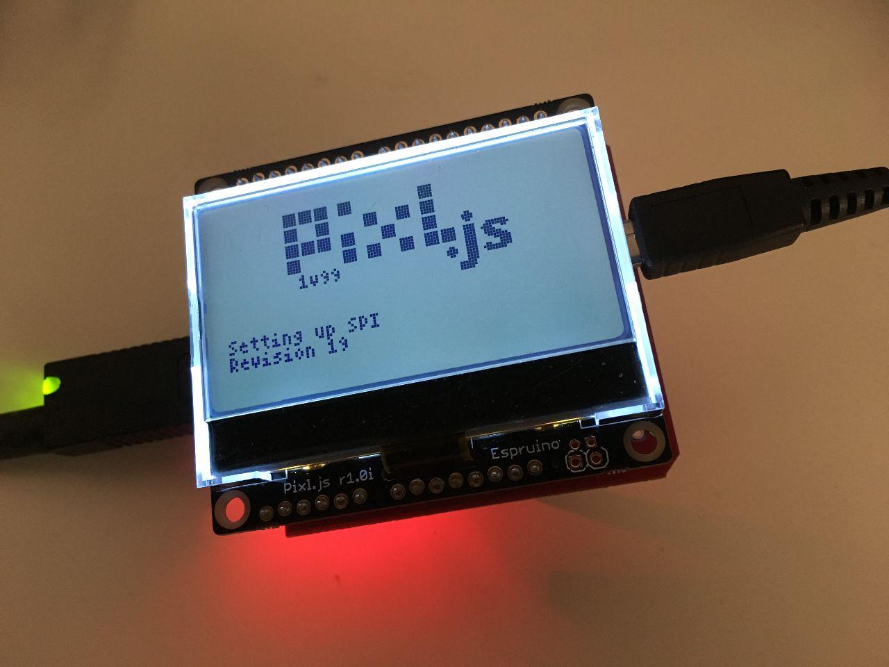
The CHIP_RESET bit in the USB_CONTROL register needs to be turned on and off for the chip to be reset. Then we wait until the USB_IRQ register turns 1 before we continue. On my Pixl.js it usually takes 1 attempt to settle. If i is 0, there's a problem:

if (reset() === 0)
  console.log('Oscillator did not settle in time');

We then set the host mode and pull down resistors:

const IRQS = {
  BUS_EVENT: 0x01,
  RWU: 0x02,
  RECEIVED_DATA_AVAILABLE: 0x04,
  SNDBAV: 0x08,
  SUS_DONE: 0x10,
  CONNECTION_DETECT: 0x20,
  FRAME: 0x40,
  HXFR_DONE: 0x80
};

setRegister(REGISTERS.MODE, 0xc1); 
setRegister(REGISTERS.HIEN, IRQS.CONNECTION_DETECT | IRQS.FRAME);

Then we check if the device is connected:

const HCTL = {
  BUSRST: 0x01,
  FRMRST: 0x02,
  SAMPLE_BUS: 0x04,
  SIGRSM: 0x08,
  RCVTOG0: 0x10,
  RCVTOG1: 0x20,
  SNDTOG0: 0x40,
  SNDTOG1: 0x80
};

setRegister(REGISTERS.HCTL, HCTL.SAMPLE_BUS);
let sampled = 0;
while(!sampled) {
  // wait for USB sample to finish
  const res = readRegister(REGISTERS.HCTL);
  sampled = res & HCTL.SAMPLE_BUS;
}

If there is a device connected, the following code will check if it's a full-speed or low-speed USB device and set the appropriate mode on the host controller chip:

busprobe() {
  const JSTATUS = 0x80;
  const KSTATUS = 0x40;
  const LOW_SPEED = 0x02;

  let busSample = readRegister(REGISTERS.HRSL);
  busSample &= (JSTATUS | KSTATUS);

  if ((busSample === KSTATUS) || (busSample === JSTATUS)) {
    const isFullSpeed = (this.readRegister(REGISTERS.MODE) & LOW_SPEED) === 0;

    if (isFullSpeed) {
      console.log('Full-speed host');
      setRegister(REGISTERS.MODE, 0xC9);
    } else {
      console.log('Low-speed host');
      setRegister(REGISTERS.MODE, 0xcb);
    }
  } else if(busSample === 0xc0) {
    console.log('Illegal state');
  } else if (busSample === 0) {
    console.log('Disconnected');
  }
}

Finally, we clear the interrupt for detecting the connection:

setRegister(REGISTERS.IRQ, IRQS.CONNECTION_DETECT);
setRegister(REGISTERS.CPU_CONTROL, 0x01); // enable interrupt pin

At the end of the week I plan to put everything in a GitHub repository, so you can get it from there if you don't want to copy and past all the bits of code from each day.

#Electronics #Tidepool

Feature image

A week ago I wrote about getting the USB host shield working on Arduino. This week it's my Tidepool hack week, for which my goal is to get the USB host shield working on the Espruino Pixl.js, so that I can build a USB-to-BLE bridge.

After plugging in the USB host shield into the Pixl.js, I had to figure out how the pins were mapped. This was easy enough, as the Sparkfun website has a schematic for the shield that shows the pin mappings:

mappings

So now we know the SPI pins are on D10 to D13. The SPI setup to talk to the board is as then simple as:

SPI1.setup({mosi:D11, miso:D12, sck:D13, order:'msb', baud: 26000000});

The order and baud parameters can be found by looking at the Arduino library's usbhost.h file. On Espruino, SPI mode 0 is the default mode.

To properly read values from the chip took me longer than necessary, as I didn't realise you have to send a second empty byte when reading a register:

function readRegister(register) {
   const result = SPI1.send([register, 0x00], D10);
   return result[1];
}

Note that we have to specify the SS pin D10 as the second parameter to the send command, and that the result is returned in the second byte that is returned. So now reading the revision of the chip you have can be done using:

console.log('Revision', readRegister(0x90));

Now were do we get the 0x90 from? If you have a look at Table 2 in the MAX3421E datasheet, you'll see that register 18 contains the chip revision number. According to the MAX3421e header file in the Arduino library, 0x90 is 18 shifted left by three bits. I still have to figure out why it has to be shifted.

If you enter the above command on the Espruino command-line interface, it should return the chip revision number – 19 in my case. This is 0x13 in hex, where the 3 is indicating it is the third revision. Version 1 is 0x01 and version 2 is 0x12.

#Electronics #Tidepool

Feature image

As it's Sunday and we've been having really great weather here in Wales lately, I spent most of the day in the garden and on the beach and not in front of the computer. This means there's no new code today, but I did want to jot down a few notes on why I decided to use a USB host controller chip (and not a Raspberry Pi) for connecting to USB devices.

I think it would be pretty easy to connect to USB devices from the Raspberry Pi's USB On-The-Go (OTG) port, and there are existing USB drivers for most serial port chips in the Linux kernel. The Pi Zero W also has Bluetooth LE and WiFi, so you can transmit data read from the USB device to a server or to a phone.

I guess I am looking for a bit more of a challenge and want to answer the question: Can a bare-metal approach to connecting USB devices work more reliably than building something on top of an operating system? Since the USB controller chip lets me develop both my own USB stack and USB drivers without having to mess around with an operating system, I'm hoping that it will result in something more reliable than the sometimes flaky USB support on desktop computers.

Modern computers are optimised for USB 3, with USB 2 support usually quite buggy, especially on new MacBooks. Many diabetes devices are still USB 2, due to the long product life cycles of medical devices, so not having good USB 2 support can be a problem.

Of course, there is power consumption as well. A Raspberry Pi consumes a significant amount of power compared to a little microcontroller with a USB controller chip. I want to see if I can build something that runs off a small LiPo battery, or maybe even a couple of coin cell batteries, that can eventually fit into a small dongle form factor. Let's see what happens.

#Electronics #Tidepool

Feature image

I've been looking for a LoRa module since I helped to install the first Things Network gateway in Swansea:

Today we installed the first @thethingsntwrk gateway for our region. We are actively contributing to the 100% open source #IoT network 😎 #ThingsConnected #Swansea #LoRaWAN #geeks pic.twitter.com/duQKy0WwWb

— TechHub Swansea (@TechHubSwansea) May 29, 2018

The Things Network is an open, community-built network using LoRaWAN technology, which allows for long-range (up to 10km) low-power wireless communication without needing a special license or monthly subscription.

This morning I saw a tweet from Tod Kurt (maintainer of the excellent node-hid Node.js library):

Cool ESP32-based LoRa module w/display for $26! as described by @VinduinoReinier at @hackaday meetup @SupplyframeDL https://t.co/CZ9vz2uPZP

— Tod E. Kurt (@todbot) June 29, 2018

The ESP32 is the successor to the ESP8266 microcontroller and contains a 32-bit microcontroller with both WiFi and Bluetooth LE. Add LoRa and an OLED screen and this is a very impressive package for less than £20. Compare this to The Thing Network's own Arduino-compatible Things Uno that only has LoRa and costs more than double the price.

I had a quick look at The Things Network forums and it looks like a lot of people are already using these, as they were released towards the end of last year. There seems to be some antenna issues, but that these can probably be fixed if you do need longer range.

#Electronics

Feature image

A week ago I wrote about building a USB host to Bluetooth LE bridge. I then ordered a Sparkfun USB Host Shield from one of the UK distributors, CPC Farnell.

The shield doesn't come without any headers, which prompted me to start organising the electronic components I have at the Swansea Hackspace, as I knew I had a spare set of headers there. I managed to find the headers last week, and soldered them on at the hackspace last night.

This morning I wanted to see if it works, so I plugged it into my old Arduino Duemilanove, released in 2009 and still going. I installed the USB Host Shield Arduino library[1] and loaded up the board_qc self-test sketch. The Arduino sketch uploaded without any problems. On the shield, I first had to connect the D7 pin to the RESET pin[2]. Also, note that there is a little power switch on the shield that you have to turn on ;)

The self-test ran without any issues. Note that to skip the GPIO test, you have to enter any character into the serial monitor and press Send. You also need to have a USB device (like a keyboard) connected during the self-test. As part of the self-test it connects to the device and displays the USB descriptor in the serial monitor. Very cool!

I then loaded up a HID keyboard sketch, and it worked flawlessly! I was able to type letters on the keyboard connected to the shield and see them appear in the serial monitor. It's pretty impressive that I could just plug a shield into a piece of hardware almost a decade old, load some code on it and it just works. Open-source hardware FTW!

usbShield2

If you'd like even more details on getting started with the USB host shield, see this great tutorial.


  1. See the README file for how to install the library ↩︎

  2. Why? I have no idea, but it was mentioned in the comments on the Sparkfun website ↩︎

#Electronics

Feature image

Over the years I've built up a collection of random electronic parts, from Arduinos to loose resistors. I've been storing them in various boxes, containers and a locker at the Swansea Hackspace, but I really can't remember what's in there anymore.

A while ago I came across a blog post on how to organise electronic parts using Partsbox.io, and since they have a free account for home users I've decided to give it a try.

I got hold of 100 small (2.25” x 3”) clear resealable bags on eBay[1], to be able to sort and label the smaller components. I wish I could justify buying a label printer[2] as they look super fun to play with, but for now I think I will just use a sharpie and blank address labels.

This is going to take some time, so I hope to give an update on my progress with a future blog post, in terms of how long it took and whether it was actually worth it.


  1. for £1.80 including P&P ↩︎

  2. like the Brother QL-700 ↩︎

#Electronics

Feature image

A shower thought I had this morning was to see if there's an Arduino shield that could act as a USB host, also known as USB OTG (On-The-Go), that I can plug that into the Espruino Pixl.js.

Why would I want to do that? Well, that would allow me to read data from USB devices, like the insulin pumps and blood glucose meters I develop drivers for in the Tidepool Uploader, display some of the data on the Pixl.js display, and then forward it onto a smart phone or computer via BLE.

Turns out there are at least two Arduino USB host shields, the official Arduino USB host shield and one made by Sparkfun. If I understand correctly, the official one connects through the Arduino's ICSP header, which is not available on the Pixl.js, leaving me with the Sparkfun option.

Both use the MAX3421E USB peripheral/host controller chip, so I'm wondering if I could eventually design a little dongle that consists of the MDBT42Q BLE module inside the Pixl.js and the USB controller chip. The BLE module is £6 in volume, and the USB controller chip between £4.50 and £6.50 depending on quantity. This makes it more expensive than a Raspberry Pi Zero W, even before you add the PCB and discrete component costs, but it should be much less power hungry.

#Electronics

Feature image

This morning I got a Pixl.js Espruino board for Father's Day. My son is not even two years old – how did he know that is exactly what I wanted?

The Pixl.js is a SoC (System-on-Chip) with a 64Mhz microcontroller and Bluetooth Low Energy module. It's an Espruino board, so you program it in JavaScript. It has a little LCD screen just like the ones in those old Nokia phones. Pixl.js's form factor is Arduino compatible, so you can plug in Arduino shields like WiFi or GSM. It can run on a coin cell battery or is powered via USB (power-only).

It works over Web Bluetooth, so you connect to it from the Espruino Web IDE. The only thing I had to do to get it working on Ubuntu 18.04 was to enable the “Experimental Web Platform Features” under chrome:flags on Chrome and then go to espruino.com/ide.

I then tried to get it working on my iPad. Unfortunately Web Bluetooth is not yet supported on Safari, but there is a WebBLE browser you can download from the app store (for £2) that does. It's a very basic browser, but all you really need it for is to run the Espruino Web IDE. That I can program a little microcontroller over Bluetooth from my iPad blows my mind!

#Electronics

Feature image

I've been adding updates to the wireless temperature sensor code I posted last week, mainly adding timestamps to the sensor readings.

canvas

I first tried using an array of objects of the form { time: <timestamp>, temp: <temperature>}, but for some reason the ESP8266 would reboot every couple of hours. My guess is that it was some kind of memory or buffer overrun issue, so I used two separate array (one for time, one for temperature) instead.

Getting accurate time from microcontrollers is notoriously difficult. At Tidepool we have an entire guide dedicated to working with timestamps coming from diabetes devices, and we use a pretty complex algorithm to convert local timestamps to UTC time.

Any microcontroller timer is susceptible to clock drift, so it was nice to discover that Espruino has a feature where it auto-updates the time on the device every time you push new code to it. While this is not necessarily going to work that well in real-world environments where you're not frequently pushing code changes, it works great for my prototype where I'm pushing new updates all the time.

Currently the prototype is sitting in our nursery, measuring the room temperature overnight to see if the baby is getting too hot, as Swansea is currently experiencing a very unusual spell of warm weather. I still can't get over how cool it is to program the ESP8266 over WiFi in another room two floors up.

So, how did I go about getting those timestamps? The first step is to set your timezone on the device, offset from UTC, so for the UK it would be 1 for UTC+1:

E.setTimeZone(1); // UTC + 1

Also remember to check the box next to “When sending code, set Espruino's clock to the current time” in the Espruino Web IDE. Getting the current time is then just regular JavaScript code:

var dt = new Date(Date.now());
var time = dt.getHours() + ':' + dt.getMinutes().toString().padStart(2,'0');
console.log(time, temp);

Note that on the ESP8266 I had to use the padStart polyfill as Espruino does not yet support ES8/ECMAScript 2017. Here is the entire script, taking sensor readings every 10 minutes and printing the timestamp and value every 5 readings:

var wifi = require('Wifi');
var http = require('http');

var led = Pin(NodeMCU.D4);
var toggle=1;
var ow = new OneWire(NodeMCU.D3);
var sensor = require("DS18B20").connect(ow);
var history = new Float32Array(60);
var timeArr = new Array(60);

function updateLed(){
  digitalWrite(led, toggle);
  toggle=!toggle;
}

// https://github.com/uxitten/polyfill/blob/master/string.polyfill.js
// https://developer.mozilla.org/en-US/docs/Web/JavaScript/Reference/Global_Objects/String/padStart
if (!String.prototype.padStart) {
    String.prototype.padStart = function padStart(targetLength,padString) {
        targetLength = targetLength>>0; //truncate if number or convert non-number to 0;
        padString = String((typeof padString !== 'undefined' ? padString : ' '));
        if (this.length > targetLength) {
            return String(this);
        }
        else {
            targetLength = targetLength-this.length;
            if (targetLength > padString.length) {
                padString += padString.repeat(targetLength/padString.length); //append to original to ensure we are longer than needed
            }
            return padString.slice(0,targetLength) + String(this);
        }
    };
}


setInterval(function() {
  updateLed();

  var temp = sensor.getTemp();
  var dt = new Date(Date.now());
  var time = dt.getHours() + ':' + dt.getMinutes().toString().padStart(2,'0');
  console.log(time, temp);
  // move history back
  for (var i = 1; i < history.length; i++) {
    history[i-1] = history[i];
    timeArr[i-1] = timeArr[i];
  }
  // insert new history at end
  history[history.length-1] = temp;
  timeArr[timeArr.length-1] = time;
}, 600000); // every 10 minutes

function onPageRequest(req, res) {
  res.writeHead(200, {'Content-Type': 'text/html'});
  res.write('<html><head><meta charset="utf-8"/><meta http-equiv="refresh" content="600"></head>'+
            '<body><canvas id="canvas" width="400" height="200" style="border:1px solid #888;"></canvas><script>');
  res.write('var d='+JSON.stringify(history)+';'+
            'var t='+JSON.stringify(timeArr)+';'+
'var c=document.getElementById("canvas").getContext("2d");'+
'c.moveTo(0,100 - (d[0]-d[d.length-1])*10);'+
'for (i in d) {'+
'var x = i*400/(d.length-1); var y = 100 - (d[i]-d[d.length-1])*10;'+
'c.lineTo(x, y);'+
'if (i % 5 === 0) {'+
'c.fillText(Number.parseFloat(d[i]).toFixed(1),x,y - 5);'+
'c.fillText(t[i],x,y + 20);}}'+
'c.stroke()'+
'</script>');
  res.end('</body></html>');
}

function onInit() {
  wifi.restore();
  http.createServer(onPageRequest).listen(80);
  console.log("Server created at " + wifi.getIP().ip);
  E.setTimeZone(1); // UTC+1, remember to select "set current time" in IDE
}

onInit();

Update: Using NTP

Justin from Swansea Hackspace pointed out that I could use NTP to get the time:

I assume this is an internet enable device, so why not just use NTP? For arduino based code the standard Time library has an example of an NTP SyncProvider callback

— Justin Mitchell (@popemadmitch) June 11, 2018

I looked it up in the Espruino docs, and low and behold, it's as easy as wifi.setSNTP('uk.pool.ntp.org', 1); (for UTC+1).

#Electronics

Feature image

I have a tiny growhouse standing outside that I've used for seedlings in the past, and potentially want to use for growing veggies hydroponically in the future. It occurred to me that I don't know how hot or cold it gets inside.

Given that it is standing against the side of the house, it gets a lot of sunlight at certain times of day and almost nothing at other times. When I know it's warm outside I open up the flap to make sure it doesn't get too hot, but I'd like to know exactly how hot it gets.

I've worked with DS18B20 temperature sensors in the past, so I knew that they are ubiquitous and pretty easy to work with. You can buy the bare chip, but I went with the waterproof version at the end of a 3 metre lead from Amazon for £3.99 including P&P. The reason for getting a temperature sensor on a lead is so that I could keep the prototype (with microcontroller on a breadboard) inside the house connected to power and just run the lead outside through the window, so that it's the only part that needs to be waterproof.

I then had to decide which microcontroller to use. Originally I wanted to use my C.H.I.P. from Next Thing Co. but it looks like they recently went bust, so I dediced to give the ESP8266 chip a try. There are a bunch of NodeMCUs at my local hackspace available for less than a fiver, and they seem like a pretty neat prototyping platform, as it's breadboard-compatible and then just plugs into USB. I've tried using the built-in Lua interpreter in the past, but I found it to be a bit flaky so decided to go down the Arduino Core route instead.

I took me forever to get the basic DS18B20 Arduino code example to work. It turns out that I had my wires swapped: There are two types of DS18B20 sensors with red, yellow and green wires and I had the less common type where the yellow wire instead of the green one is ground. One good thing came out of this: On that page describing the sensor types I discovered that there is an ESP8266 port of Espruino, which would allow me to write actual JavaScript code, not “NodeJS-like” code which is actually Lua[1].

Man, was this a game changer. Espruino has great example code, and a simple web-based editor which allows you to connect to the device over WiFi and update your code over the air (OTA) almost instantly. Compared to the Arduino Core where it can take quite long to update your code over USB, this felt magical. I know Arduino Core has OTA capability too, but I haven't tried it yet.

So, without further ado, here is the code I use to connect to the temperature sensor, cobbled together from various Espruino examples. It takes a sensor reading every minute (in Celsius) and runs a web server that displays a temperature graph. It also toggles the on-board LED when it takes a reading. I specifically did not want to use an IoT platform/service, as they don't tend to stay around for long and the ESP8266 is perfectly capable of running its own web server:

temperature graph

var wifi = require('Wifi');
var http = require('http');

var led = Pin(NodeMCU.D4); // on-board LED
var toggle = 1;
var ow = new OneWire(NodeMCU.D3); // data pin connected to D3
var sensor = require("DS18B20").connect(ow);
var history = new Float32Array(30); // store 30 readings

function updateLed(){
  digitalWrite(led, toggle);
  toggle=!toggle;
}

setInterval(function() {
  updateLed();

  var temp = sensor.getTemp();
  console.log(temp);
  // move history back
  for (var i=1; i<history.length; i++)
    history[i-1]=history[i];
  // insert new history at end
  history[history.length-1] = temp;
}, 60000);

function onPageRequest(req, res) {
  res.writeHead(200, {'Content-Type': 'text/html'});
  res.write('<html><head><meta charset="utf-8"/><meta http-equiv="refresh" content="60"></head>'+
            '<body><canvas id="canvas" width="200" height="200" style="border:1px solid #888;"></canvas><script>');
  res.write('var d='+JSON.stringify(history)+';'+
'var c=document.getElementById("canvas").getContext("2d");'+
'c.moveTo(0,100 - (d[0]-d[d.length-1])*10);'+
'for (i in d) {'+
'var x = i*200/(d.length-1); var y = 100 - (d[i]-d[d.length-1])*10;'+
'c.lineTo(x, y);'+
'if (i % 5 === 0) c.fillText(Number.parseFloat(d[i]).toFixed(1),x,y - 2);}'+
'c.stroke()'+
'</script>');
  res.end('</body></html>');
}

function onInit() {
  wifi.restore();
  http.createServer(onPageRequest).listen(80);
  console.log("Server created at " + wifi.getIP().ip);
}

onInit();

What's also great about Espruino is that it saves your WiFi credentials separately on the flash memory, which means you don't accidentally expose them in your example code. 😉


  1. which is where NodeMCU gets its name from ↩︎

#Hydroponics #Electronics