USB host shield on Espruino: Part 1
A week ago I wrote about getting the USB host shield working on Arduino. This week it's my Tidepool hack week, for which my goal is to get the USB host shield working on the Espruino Pixl.js, so that I can build a USB-to-BLE bridge.
After plugging in the USB host shield into the Pixl.js, I had to figure out how the pins were mapped. This was easy enough, as the Sparkfun website has a schematic for the shield that shows the pin mappings:

So now we know the SPI pins are on D10 to D13. The SPI setup to talk to the board is as then simple as:
SPI1.setup({mosi:D11, miso:D12, sck:D13, order:'msb', baud: 26000000});
The order and baud parameters can be found by looking at the Arduino library's usbhost.h file. On Espruino, SPI mode 0 is the default mode.
To properly read values from the chip took me longer than necessary, as I didn't realise you have to send a second empty byte when reading a register:
function readRegister(register) {
   const result = SPI1.send([register, 0x00], D10);
   return result[1];
}
Note that we have to specify the SS pin D10 as the second parameter to the send command, and that the result is returned in the second byte that is returned. So now reading the revision of the chip you have can be done using:
console.log('Revision', readRegister(0x90));
Now were do we get the 0x90 from? If you have a look at Table 2 in the MAX3421E datasheet, you'll see that register 18 contains the chip revision number. According to the MAX3421e header file in the Arduino library, 0x90 is 18 shifted left by three bits. I still have to figure out why it has to be shifted.
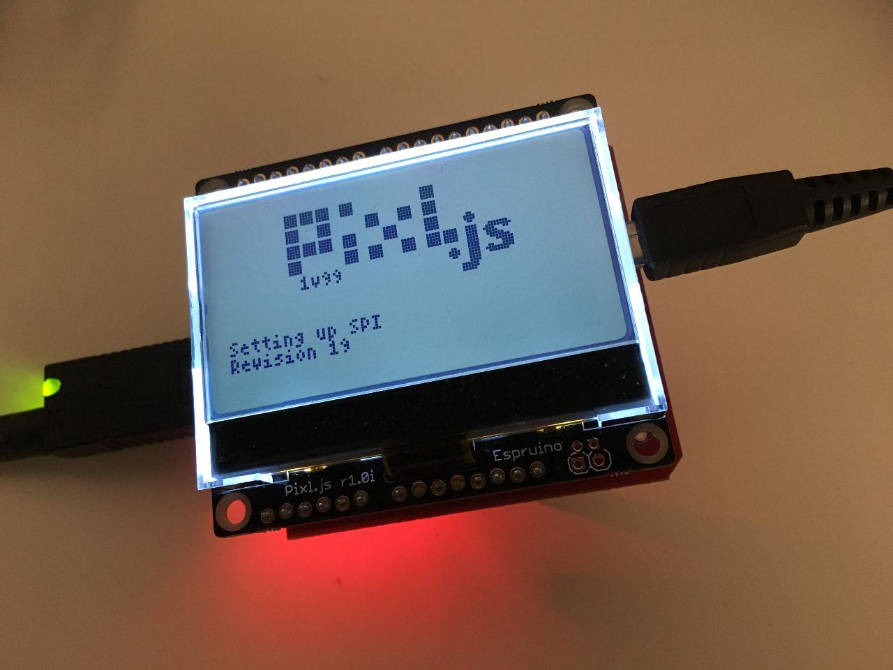
If you enter the above command on the Espruino command-line interface, it should return the chip revision number – 19 in my case. This is 0x13 in hex, where the 3 is indicating it is the third revision. Version 1 is 0x01 and version 2 is 0x12.
Comment on this post