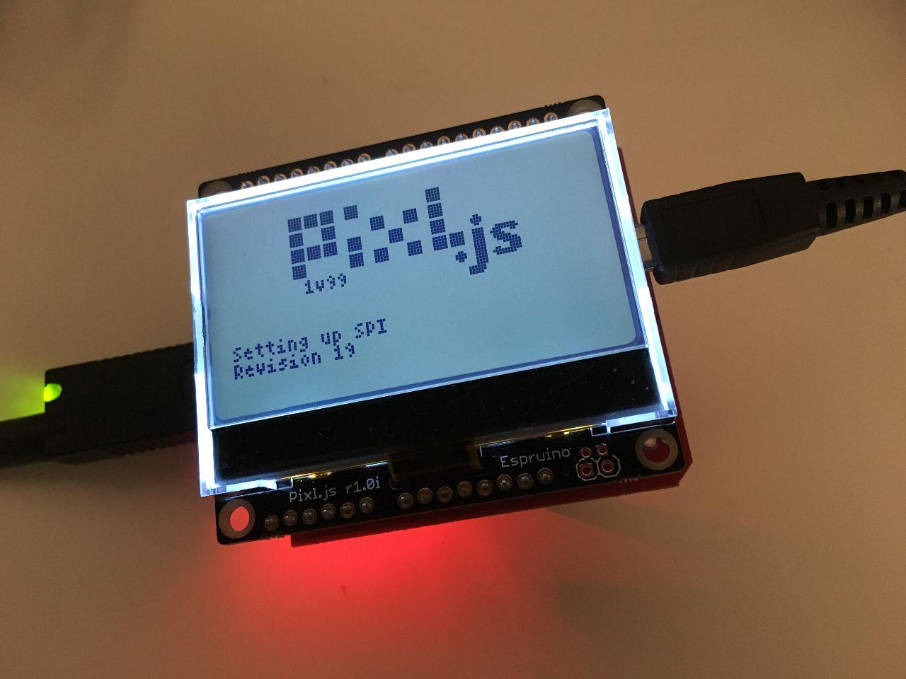
USB host shield on Espruino: Part 2

Yesterday we looked at how to connect to the USB host shield and read the register that contains the chip revision number. Today we'll look at how to initialise the USB connection with the device.
We already have a way to read registers on the USB host controller chip, but we also need a way to set registers:
setRegister(register, command) {
    SPI1.write([register | 0x02, command], D10);
}
It's similar to reading a register, except that we use the SPI1.write command since we're not expecting anything to be returned. We also send the SS pin D10 as a parameter. Now we can define some constants and set up full-duplex communication:
const REGISTERS = {
  RCVFIFO: 0x08,
  SUDFIFO: 0x20,
  RCVBC: 0x30,
  USB_CONTROL: 0x78,
  CPU_CONTROL: 0x80,
  PIN_CONTROL: 0x88,
  USB_IRQ: 0x68,
  IRQ: 0xc8,
  MODE: 0xd8,
  HIEN: 0xd0,
  PERADDR: 0xe0,
  HCTL: 0xe8,
  HXFR: 0xf0,
  HRSL: 0xf8,
};

const OPTIONS = {
  LEVEL_INTERRUPT: 0x08,
  FULL_DUPLEX: 0x10,
};

setRegister(REGISTERS.PIN_CONTROL, OPTIONS.FULL_DUPLEX | OPTIONS.LEVEL_INTERRUPT);
Those are not all the registers that are available. We'll add to the list as we go along. For the full list of registers see Table 2 in the MAX34321E datasheet. Now we need to reset the chip:
const COMMANDS = {
  CHIP_RESET: 0x20,
};

reset() {
  this.setRegister(REGISTERS.USB_CONTROL, COMMANDS.CHIP_RESET);
  this.setRegister(REGISTERS.USB_CONTROL, 0x00);
  let i = 0;
  while((this.readRegister(REGISTERS.USB_IRQ) & 0x01) === 0) {
    i++;
  }
  console.log(i, 'attempts to settle');
  return i;
}
The CHIP_RESET bit in the USB_CONTROL register needs to be turned on and off for the chip to be reset. Then we wait until the USB_IRQ register turns 1 before we continue. On my Pixl.js it usually takes 1 attempt to settle. If i is 0, there's a problem:
if (reset() === 0)
  console.log('Oscillator did not settle in time');
We then set the host mode and pull down resistors:
const IRQS = {
  BUS_EVENT: 0x01,
  RWU: 0x02,
  RECEIVED_DATA_AVAILABLE: 0x04,
  SNDBAV: 0x08,
  SUS_DONE: 0x10,
  CONNECTION_DETECT: 0x20,
  FRAME: 0x40,
  HXFR_DONE: 0x80
};

setRegister(REGISTERS.MODE, 0xc1);
setRegister(REGISTERS.HIEN, IRQS.CONNECTION_DETECT | IRQS.FRAME);
Then we check if the device is connected:
const HCTL = {
  BUSRST: 0x01,
  FRMRST: 0x02,
  SAMPLE_BUS: 0x04,
  SIGRSM: 0x08,
  RCVTOG0: 0x10,
  RCVTOG1: 0x20,
  SNDTOG0: 0x40,
  SNDTOG1: 0x80
};

setRegister(REGISTERS.HCTL, HCTL.SAMPLE_BUS);
let sampled = 0;
while(!sampled) {
  // wait for USB sample to finish
  const res = readRegister(REGISTERS.HCTL);
  sampled = res & HCTL.SAMPLE_BUS;
}
If there is a device connected, the following code will check if it's a full-speed or low-speed USB device and set the appropriate mode on the host controller chip:
busprobe() {
  const JSTATUS = 0x80;
  const KSTATUS = 0x40;
  const LOW_SPEED = 0x02;

  let busSample = readRegister(REGISTERS.HRSL);
  busSample &= (JSTATUS | KSTATUS);

  if ((busSample === KSTATUS) || (busSample === JSTATUS)) {
    const isFullSpeed = (this.readRegister(REGISTERS.MODE) & LOW_SPEED) === 0;

    if (isFullSpeed) {
      console.log('Full-speed host');
      setRegister(REGISTERS.MODE, 0xC9);
    } else {
      console.log('Low-speed host');
      setRegister(REGISTERS.MODE, 0xcb);
    }
  } else if(busSample === 0xc0) {
    console.log('Illegal state');
  } else if (busSample === 0) {
    console.log('Disconnected');
  }
}
Finally, we clear the interrupt for detecting the connection:
setRegister(REGISTERS.IRQ, IRQS.CONNECTION_DETECT);
setRegister(REGISTERS.CPU_CONTROL, 0x01); // enable interrupt pin
At the end of the week I plan to put everything in a GitHub repository, so you can get it from there if you don't want to copy and past all the bits of code from each day.
Comment on this post