Gerrit Niezen

tidepool

Feature image

Yesterday I mentioned starting on a Silicon Labs CP2102 user-space driver for Node.js. Well, I just managed to successfully read data from the device! The source code for the driver is already on GitHub, but I still need to write up usage instructions and do some testing.

I wrote it as a kind of WebUSB to node-usb interface, so that I can re-use parts of the code to easily port WebUSB drivers over to Node.js, or maybe I could even package the interface up as an NPM package? Then you can re-use your WebUSB drivers in Node.js by just by adding one line of code to import this package.

One thing that I found non-intuitive was that after sending a request for data as a USB bulk out transfer, you then either need to create another USB bulk in transfer to read data, or use node-usb's startPoll() function, which essentially starts polling for data on the IN endpoint. Also, if you're using endpoint 1, 0x01 is OUT and 0x81 is IN. You may find this code useful if you're trying to create a USB request type:

function getRequestType(direction, requestType, recipient) {
  const TYPES = {
    standard: 0x00,
    class: 0x01,
    vendor: 0x02,
    reserved: 0x03,
  };

  const RECIPIENTS = {
    device: 0x00,
    interface: 0x01,
    endpoint: 0x02,
    other: 0x03,
  };

  const DIRECTION = {
    'host-to-device': 0x00,
    'device-to-host': 0x01,
  };

  return (DIRECTION[direction] << 7) || (TYPES[requestType] << 5) || RECIPIENTS[recipient];
}

I hope the stuff I learned today will help me when I continue my project to getting a USB host shield working on Espruino...

#Tidepool

Comment on this post

Feature image

I found these battery holders on Thingiverse. I printed the one to hold AAA batteries a while ago, and printed the AA one last night. The thing on the right is my honeycomb cable holder for USB cables.

AA_holder

I go through a lot of batteries for my Tidepool work, given that I have dozens of glucose meters and insulin pumps that need to be powered. It's nice to have a compact and stackable design to keep them all in one place.

When I eventually start using an different colour filament I can print the lettering that goes on the front. For now, it looks fine even without the different colours.

#Making #Tidepool

Comment on this post

Feature image

When you need to install a driver to get your USB device working, this driver is installed in kernel-space. On macOS this is called a kernel extension , which is a nice descriptive term. On Linux it's usually not even necessary not install anything, as support for almost every USB device is already built into the kernel. On Windows, the situation is ... a bit different.

With the release of macOS High Sierra, Apple is making it really difficult to install kernel extensions. Some have even called it a kextpocalypse. While I think Apple have made some serious UX mistakes in implementing this, I do agree with the sentiment regarding security. Kernel-space drivers run in a highly privileged mode which can seriously screw with your machine.

There is a great macOS app called Serial for connecting to serial USB devices. The first time I used it felt like magic, as it was able to connect to devices without having to install any kernel extensions. I contacted the developer and he explained that he basically wrote user-space drivers for all the devices.

Yesterday I added a user-space USB driver for CDC-ACM devices[1] written in Node.js by Nordic to the Tidepool Uploader. It works great on Linux and macOS, but not on Windows.

The reason is that even if you have a user-space driver, you still need to install a USB driver on Windows. That is because Windows apparently can't tell on its own that a USB device is a USB device and you always have to install a driver to tell it that.

The result of this is that Microsoft essentially requires anyone who want to use a USB device (that doesn't have a driver already built into Windows), to have administrator privileges and install a driver to use said device. Contrast that with macOS, where Apple effectively said with High Sierra that they don't want people to install drivers, so that user-space drivers are basically encouraged.


  1. that includes the Dexcom receiver and Tandem insulin pump we support at Tidepool ↩︎

#Tidepool

Comment on this post

I still haven't successfully received data from the meter, but analysing the USB packets using the logic analyser that I started with yesterday has been super helpful.

After I discovered yesterday that there wasn't any USB bulk transfer data being sent on the bus, I had a look at the relevant code and it turns out that I didn't define two of the registers correctly. Once that was fixed I could successfully load data into the SNDFIFO register, put the number of bytes to be sent in the SNDBC register, and send it on its way. I verified using the logic analyser that my bulk transfer data was now appearing on the USB bus.

Unfortunately, nothing is coming back yet. I figured that maybe I should try to sniff the packets between my WebUSB app and the cable, so I opened up my USB hub:

usbHub

After my initial surprise to discover that the PCB is purple[1], I connected the logic analyser the same way I did yesterday – straight to the USB connector.

And guess what? It worked great. I can see USB traffic between an app on my computer and a device connected to my USB hub, down to the bit-level. This means I can even sniff USB traffic on macOS El Capitan and Sierra, where Wireshark doesn't work. Now to figure out what is different between the WebUSB-to-device and Espruino-to-device communication.


  1. I've only ever seen purple PCBs from the awesome OSH Park ↩︎

#Electronics #Tidepool

Comment on this post

Today I want look at analysing what exactly is happening on the USB bus when we send and receive messages, to make sure that what I think is happening is actually happening. On a Windows or Linux machine this can be done with Wireshark. I think it may also be possible on macOS since the High Sierra release. However, we're working with a USB host controller chip, so Wireshark is a no-go.

There are professional-grade USB analysers from Total Phase that start at around \$475 (for USB 2.0 full-speed 12MBps) all the way up to \$6000 (for USB 3.0 5Gbps). While we should be able to use the 12Mbps analyser, I wanted to see if it's possible to use a little $10 logic analyser to analyse USB traffic:

This little $10 logic analyzer arrived on Friday and I am looking forward on using it with the awesome open-source @sigrokproject software. It would be great if I can get it to sniff some low-speed USB traffic. pic.twitter.com/Awhb9pSzvm

— Gerrit Niezen (@gendor) October 2, 2017

That was almost ten months go, and since I'm still struggling to figure out why I'm not getting any results back from the meter, I decided to give it a try. This 8-channel 24MHz logic analyser was only £13.44 (including P&P). It comes with a set of test hook clips, which I was able to connect to the USB port surprisingly easy:

hooksusb

The pins at the back of the USB connector has just enough space so that you can attach the hook clips. The USB connector pinout is +5V, D-, D+ and GND, so I had another look at the schematic on the Sparkfun website. It showed that D+ and D- are connected to resistors, while +5V is connected to an overcurrent protection device. Based on this I could identify which side was +5V and connected the hook clips. I connected D- to channel 0 on the logic analyser and D+ to channel 1, and GND to ground. I also connected D2 to CH2 to use as a trigger:

logicSetup

Now it was time to install the sigrok PulseView software. I chose “fx2lafw” as the driver for my analyser, and when it successfully connected, defined the three channels for D-, D+ and the trigger. I selected the maximum available frequency (24 MHz) and 1 G samples, which should allow for 42 seconds of sample time. I then added the USB signalling decoder with USB packet and USB request decoding, and specified the appropriate signals and full-speed signalling:

sigrok1

I also added digitalWrite(D2, 1) in my code where I wanted the trigger to occur. I started up the Espruino code and clicked on Run:

firstSession

I was successfully sniffing USB packets between the TUSB3410 chip in the cable and my USB host controller chip! After verifying that most of the packets I was sending were actually appearing on the bus, I noticed that my bulk out transfers were missing:

missingPackets

Above you can hopefully make out the setup packet 40 05 00 00 03 00 0A 00, which should be followed by some data. Instead it is followed by the “close” packet 40 07 00 00 03 00 00 00. So maybe that is where I should start looking as to why things aren't working!

#Electronics #Tidepool

Comment on this post

I spent a couple of hours this afternoon and again this evening trying to get the TUSB3410 driver to work. I am now able to successfully communicate with the TUSB3410 chip inside the USB cable, set up some configuration parameters and send data to the glucose meter connected to the cable. The final step, actually getting data back from the chip, is still not working.

Basically, I'm getting a 0x0D error back from the USB host controller chip which, according to the data sheet, is a “J-state instead of response” error. What this actually means is not explained anywhere in the documentation, but I did come across a blog post from 2010 that indicates it may be an issue with my “Set Configuration” control transfer message.

Part of my debugging process involved actually using the WebUSB driver I wrote inside the browser and then using Wireshark to sniff the USB packets on the bus. This way I was able to make sure that I'm sending the exact same bytes to the USB controller chip. However, on Linux and macOS it wasn't necessary to set the configuration, so I'm not sure why it's different now.

As a quick aside: To connect to the TUSB3410 chip via WebUSB on Linux, I first had to disable the built-in TUSB3410 kernel driver that claims the device when it's plugged in. To do this, you can type lsmod | grep 3410 to find the name of the kernel driver. On my machine it's ti_usb_3410_5052. To disable it, type sudo modprobe -r ti_usb_3410_5052. To re-enable it, type sudo modprobe ti_usb_3410_5052.

#Electronics #Tidepool

Comment on this post

Today there won't be any new code, as I'm still trying to get it to work. After yesterday's successes in reading the device and configuration descriptors, I decided to implement a USB driver for the TUSB3410 chip from Texas Instruments (TI) on top of the USB stack I've written so far.

During my previous Tidepool hack week last year I wrote a WebUSB driver for the TI chip. This chip is used in the USB cables that communicate with the Abbott FreeStyle series of blood glucose meters, and there is no macOS USB driver available. Using WebUSB, I was able to successfully download data from a meter on macOS. Now I would like to see if I can get data from the meter using the Espruino and the USB host controller chip.

I'm writing the the USB stack for the controller chip so that it looks like the WebUSB interface. Therefore it should be pretty easy to re-use that driver code, as long as the USB stack underneath behaves the same as WebUSB.

While working on this today, I realised there are still a number of functions I need to implement in my USB stack, like control transfers that send data. When I get this to work and retrieve data from the meter successfully, I will put the code on GitHub and see if I can write an explainer here.

#Electronics #Tidepool

Comment on this post

Feature image

Now that we can connect to a device using the USB controller chip with Espruino, we can start reading the USB configuration and device descriptors. These descriptors give us more information about the device, for example its USB vendor ID and product ID. We need to follow the following series of steps before we can start sending and receiving data:

  1. According to the USB spec we first need to wait 200ms after connecting to the device and then reset the device bus.
  2. We then wait until the device is reset and start the Start-Of-Frame (SOF) marker. This is a timing reference that is sent at 1 ms intervals at full speed.
  3. According to the USB spec we then need to wait 20 ms after the device is reset and check if the SOF marker was received.
setTimeout( () => {
  console.log('Resetting device bus');
  this.setRegister(REGISTERS.HCTL, HCTL.BUS_RESET);
  while((this.readRegister(REGISTERS.HCTL) & HCTL.BUS_RESET) !== 0) { }

  console.log('Start SOF');
  const result = this.readRegister(REGISTERS.MODE) | HCTL.SOFKAENAB;
  this.setRegister(REGISTERS.MODE, result);

  setTimeout( () => {
    if (this.readRegister(REGISTERS.IRQ) & IRQS.FRAME) {
      // first SOF received
      console.log('SOF received');

      // get descriptors here

    }
  }, 20); // USB spec says wait 20ms after reset
}, 200);

As soon as we have the first SOF marker, we can start reading the descriptors using a control transfer. To send and receive data, everything in USB land happens in terms of transfers, of which there are four types:

  • Control transfers — send a defined request to the device, for example to read information about a device or select configuration settings
  • Interrupt transfers — low latency data, for example keypresses or mouse movements; also the the only way for low-speed devices to send data
  • Bulk transfers — data where a delay can be tolerated, but the fastest way to send data if the bus is idle
  • Isochronous transfers — guaranteed delivery time, but no error correction, so useful for streaming audio and video

To do a control transfer, we need to set the address register and create an eight-byte setup packet containing the following:

  • The request type, i.e, 'vendor', 'standard' or 'class'
  • The request itself, for example 0x06 is USB_REQUEST_GET_DESCRIPTOR
  • A value field with two bytes containing request-specific information
  • A length field specifying the number of data bytes

In the following code example we also introduce two other functions. sendBytes(register, bytes) is used to send multiple bytes, which we place into the USB chip's SUDFIFO register. After that dispatchPacket(token, ep) sends the packet on its way.

sendBytes(register, bytes) {
 SPI1.write(E.toUint8Array(register | 0x02, bytes), SS);
}

dispatchPacket(token, ep) {
 let nakCount = 0;
 let retryCount = 0;

 const abortTimer = setTimeout( () => {
   console.log('Timeout error');
   return(new Error('Timeout error'));
 }, 5000);

 this.setRegister(REGISTERS.HXFR, token | ep);
 while (this.readRegister(REGISTERS.IRQ) & IRQS.HXFR_DONE === 0) { }

 // clear interrupt
 clearTimeout(abortTimer);
 this.setRegister(REGISTERS.IRQ, IRQS.HXFR_DONE);

 const transferResult = this.readRegister(REGISTERS.HRSL) & 0x0f;

 if (transferResult === HRSL.NAK) {
   console.log('NAK');
   nakCount++;
   if (nakCount > USB_NAK_LIMIT) {
     return(new Error('NAK error'));
   }
 } else if (transferResult === HRSL.TIMEOUT) {
   console.log('Timeout, retrying..');
   retryCount++;
   if (retryCount > USB_RETRY_LIMIT) {
     return(new Error('Timeout error'));
   }
 }
 return transferResult;
}

controlTransferIn(setup, length) {
 const addr = 0;

 this.setRegister(REGISTERS.PERADDR, addr);

 let setupPacket = new Uint8Array(8);
 setupPacket[0] = REQUEST_TYPE[setup.requestType];
 setupPacket[1] = setup.request;
 storeShort(setup.value, setupPacket, 2);
 storeShort(setup.index, setupPacket, 4);
 setupPacket[6] = length;
 console.log('Setup packet:', bytes2hex(setupPacket));

 this.sendBytes(REGISTERS.SUDFIFO, setupPacket);
 let err = this.dispatchPacket(TOKENS.SETUP, 0);
 if (err) {
   console.log('Setup packet error:', err);
 }
}

Now that we have the control transfer set up and sent to the device, we need to transfer the data bytes in. This is done in the transferIn(ep, length) function. We first set the receive toggle , which is used for USB signaling. We then dispatch the IN packet to indicate that we want to read the data bytes. We then check that the data is available by checking the IRQ register for IRQS.RECEIVED_DATA_AVAILABLE. We then ready the packet size from the RCVBC register, and finally read the data bytes themselves from the RCVFIFO register. We clear the interrupt and continue reading until all the data bytes are read

transferIn(ep, length) {
  let transferLength = 0;
  let data = new Uint8Array(length);

  this.setRegister(REGISTERS.HCTL, receiveToggle);
  while (1) {
    const err = this.dispatchPacket(TOKENS.IN, ep);
    if (err) {
      console.log('Error:', err);
      return(err);
    }
    if (this.readRegister(REGISTERS.IRQ) & IRQS.RECEIVED_DATA_AVAILABLE === 0) {
      return(new Error('Receive error'));
    }
    const packetSize = this.readRegister(REGISTERS.RCVBC);
    console.log('Packet size:', packetSize);
    data.set(this.readBytes(REGISTERS.RCVFIFO, packetSize), transferLength);
    this.setRegister(REGISTERS.IRQ, IRQS.RECEIVED_DATA_AVAILABLE); // clear interrupt
    transferLength += packetSize;

    if ((packetSize < 8) || (transferLength >= length)) {
      return { data: data };
    }
  }
}

OK, now that we have defined all the functions we'll need, we can specify the setup packet to get the device descriptor and perform our control transfer:

const getDeviceDescriptor = {
    requestType: 'vendor',
    recipient: 'device',
    request: 0x06, // USB_REQUEST_GET_DESCRIPTOR
    value: 0x0100, // USB_DESCRIPTOR_DEVICE = 0x01
    index: 0x0000
};

usb.controlTransferIn(getDeviceDescriptor, 18);
let results = usb.transferIn(0, 18);
console.log('Get device descriptor:', results.data);

Note that we already know that the device descriptor is 18 bytes long. The configuration descriptor can be of variable length, so we start with reading the first four bytes, which contain the length, and then do another control transfer to retrieve all the data bytes:

const getConfigDescriptor = {
  requestType: 'vendor',
  recipient: 'device',
  request: 0x06, // USB_REQUEST_GET_DESCRIPTOR
  value: 0x0202, // USB_DESCRIPTOR_CONFIGURATION = 0x02, conf = 0x02
  index: 0x0000
};

// Get config descriptor length
usb.controlTransferIn(getConfigDescriptor, 4);
results = usb.transferIn(0, 4);
const configDescriptorLength = extractShort(results.data, 2);
console.log('Config descriptor length:', configDescriptorLength);

usb.controlTransferIn(getConfigDescriptor, configDescriptorLength);
results = usb.transferIn(0, configDescriptorLength);
console.log('Data:', results.data);

Wow, that was quite a bit of code! Well, at least we will be able to re-use quite a few of the functions when we need to perform the other USB transfers. If you'd like to read more about USB, I can definitely recommend Jan Axelson's book USB Complete.

#Electronics #Tidepool

Comment on this post
Feature image

Yesterday we looked at how to connect to the USB host shield and read the register that contains the chip revision number. Today we'll look at how to initialise the USB connection with the device.

We already have a way to read registers on the USB host controller chip, but we also need a way to set registers:

setRegister(register, command) {
    SPI1.write([register | 0x02, command], D10);
}

It's similar to reading a register, except that we use the SPI1.write command since we're not expecting anything to be returned. We also send the SS pin D10 as a parameter. Now we can define some constants and set up full-duplex communication:

const REGISTERS = {
  RCVFIFO: 0x08,
  SUDFIFO: 0x20,
  RCVBC: 0x30,
  USB_CONTROL: 0x78,
  CPU_CONTROL: 0x80,
  PIN_CONTROL: 0x88,
  USB_IRQ: 0x68,
  IRQ: 0xc8,
  MODE: 0xd8,
  HIEN: 0xd0,
  PERADDR: 0xe0,
  HCTL: 0xe8,
  HXFR: 0xf0,
  HRSL: 0xf8,
};

const OPTIONS = {
  LEVEL_INTERRUPT: 0x08,
  FULL_DUPLEX: 0x10,
};

setRegister(REGISTERS.PIN_CONTROL, OPTIONS.FULL_DUPLEX | OPTIONS.LEVEL_INTERRUPT);

Those are not all the registers that are available. We'll add to the list as we go along. For the full list of registers see Table 2 in the MAX34321E datasheet. Now we need to reset the chip:

const COMMANDS = {
  CHIP_RESET: 0x20,
};
    
reset() {
  this.setRegister(REGISTERS.USB_CONTROL, COMMANDS.CHIP_RESET);
  this.setRegister(REGISTERS.USB_CONTROL, 0x00);
  let i = 0;
  while((this.readRegister(REGISTERS.USB_IRQ) & 0x01) === 0) {
    i++;
  }
  console.log(i, 'attempts to settle');
  return i;
}

The CHIP_RESET bit in the USB_CONTROL register needs to be turned on and off for the chip to be reset. Then we wait until the USB_IRQ register turns 1 before we continue. On my Pixl.js it usually takes 1 attempt to settle. If i is 0, there's a problem:

if (reset() === 0)
  console.log('Oscillator did not settle in time');

We then set the host mode and pull down resistors:

const IRQS = {
  BUS_EVENT: 0x01,
  RWU: 0x02,
  RECEIVED_DATA_AVAILABLE: 0x04,
  SNDBAV: 0x08,
  SUS_DONE: 0x10,
  CONNECTION_DETECT: 0x20,
  FRAME: 0x40,
  HXFR_DONE: 0x80
};

setRegister(REGISTERS.MODE, 0xc1); 
setRegister(REGISTERS.HIEN, IRQS.CONNECTION_DETECT | IRQS.FRAME);

Then we check if the device is connected:

const HCTL = {
  BUSRST: 0x01,
  FRMRST: 0x02,
  SAMPLE_BUS: 0x04,
  SIGRSM: 0x08,
  RCVTOG0: 0x10,
  RCVTOG1: 0x20,
  SNDTOG0: 0x40,
  SNDTOG1: 0x80
};

setRegister(REGISTERS.HCTL, HCTL.SAMPLE_BUS);
let sampled = 0;
while(!sampled) {
  // wait for USB sample to finish
  const res = readRegister(REGISTERS.HCTL);
  sampled = res & HCTL.SAMPLE_BUS;
}

If there is a device connected, the following code will check if it's a full-speed or low-speed USB device and set the appropriate mode on the host controller chip:

busprobe() {
  const JSTATUS = 0x80;
  const KSTATUS = 0x40;
  const LOW_SPEED = 0x02;

  let busSample = readRegister(REGISTERS.HRSL);
  busSample &= (JSTATUS | KSTATUS);

  if ((busSample === KSTATUS) || (busSample === JSTATUS)) {
    const isFullSpeed = (this.readRegister(REGISTERS.MODE) & LOW_SPEED) === 0;

    if (isFullSpeed) {
      console.log('Full-speed host');
      setRegister(REGISTERS.MODE, 0xC9);
    } else {
      console.log('Low-speed host');
      setRegister(REGISTERS.MODE, 0xcb);
    }
  } else if(busSample === 0xc0) {
    console.log('Illegal state');
  } else if (busSample === 0) {
    console.log('Disconnected');
  }
}

Finally, we clear the interrupt for detecting the connection:

setRegister(REGISTERS.IRQ, IRQS.CONNECTION_DETECT);
setRegister(REGISTERS.CPU_CONTROL, 0x01); // enable interrupt pin

At the end of the week I plan to put everything in a GitHub repository, so you can get it from there if you don't want to copy and past all the bits of code from each day.

#Electronics #Tidepool

Comment on this post

Feature image

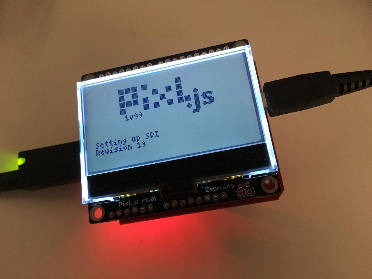
A week ago I wrote about getting the USB host shield working on Arduino. This week it's my Tidepool hack week, for which my goal is to get the USB host shield working on the Espruino Pixl.js, so that I can build a USB-to-BLE bridge.

After plugging in the USB host shield into the Pixl.js, I had to figure out how the pins were mapped. This was easy enough, as the Sparkfun website has a schematic for the shield that shows the pin mappings:

mappings

So now we know the SPI pins are on D10 to D13. The SPI setup to talk to the board is as then simple as:

SPI1.setup({mosi:D11, miso:D12, sck:D13, order:'msb', baud: 26000000});

The order and baud parameters can be found by looking at the Arduino library's usbhost.h file. On Espruino, SPI mode 0 is the default mode.

To properly read values from the chip took me longer than necessary, as I didn't realise you have to send a second empty byte when reading a register:

function readRegister(register) {
   const result = SPI1.send([register, 0x00], D10);
   return result[1];
}

Note that we have to specify the SS pin D10 as the second parameter to the send command, and that the result is returned in the second byte that is returned. So now reading the revision of the chip you have can be done using:

console.log('Revision', readRegister(0x90));

Now were do we get the 0x90 from? If you have a look at Table 2 in the MAX3421E datasheet, you'll see that register 18 contains the chip revision number. According to the MAX3421e header file in the Arduino library, 0x90 is 18 shifted left by three bits. I still have to figure out why it has to be shifted.

If you enter the above command on the Espruino command-line interface, it should return the chip revision number – 19 in my case. This is 0x13 in hex, where the 3 is indicating it is the third revision. Version 1 is 0x01 and version 2 is 0x12.

#Electronics #Tidepool

Comment on this post